
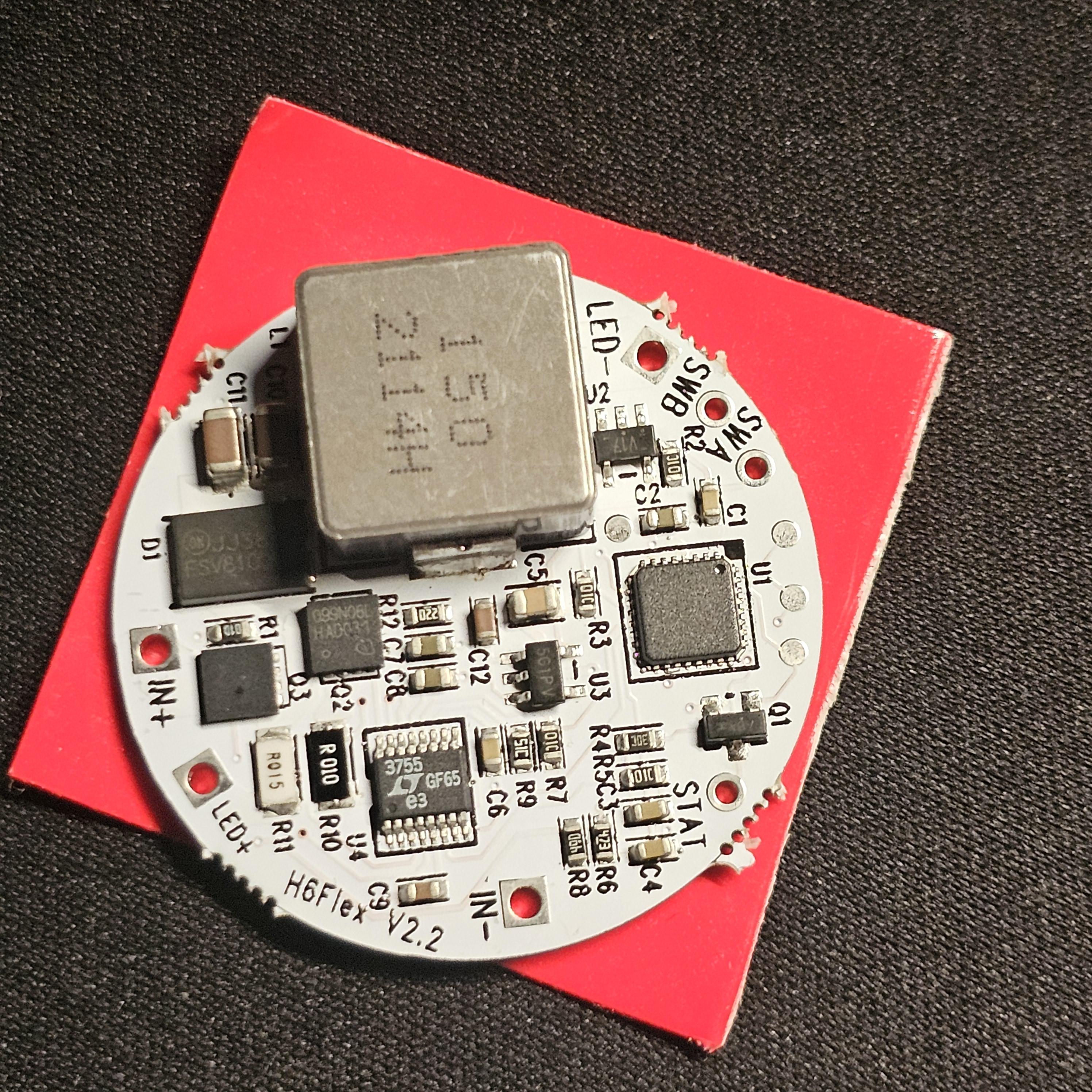
Hi everyone, Yesterday I started working on the initial design of my custom dive light head in SolidWorks. I placed a Cree XHP50 HD on a SinkPAD MCPCB and then added a LEDiL CUTE-3 optic. That's when I noticed a problem. The optic manufacturer doesn't specify the maximum LED height it's designed for. I only have about 2 mm of space between the MCPCB and the optic, while the XHP50 HD is a little over 3 mm tall because of the silicone dome. So my first question is: Would it make more sense to remove the silicone dome (dedome the LED), or should I simply design and 3D-print spacers for the optic legs? The bigger issue is that I have no idea what the optimal distance should be between the top of the LED and the optic. Is there any recommended clearance, or is it just a matter of trial and error? Has anyone here used a CUTE-3 optic with an XHP50 before? My second question is about the driver. I'm using a TaskLED H6Flex, and I can see it has SW terminals. Can I connect a piezo switch directly to those inputs, or do I need a separate on/off control board? This is a canister dive light, so the battery is external and there's plenty of room inside the head if I need an additional board. I'd also like to use a piezo switch with an illuminated ring so it's easier to find the button in complete darkness underwater. I've attached a couple of photos of the current design. Any advice would be greatly appreciated.
here some fotos;
by Snajperitto91