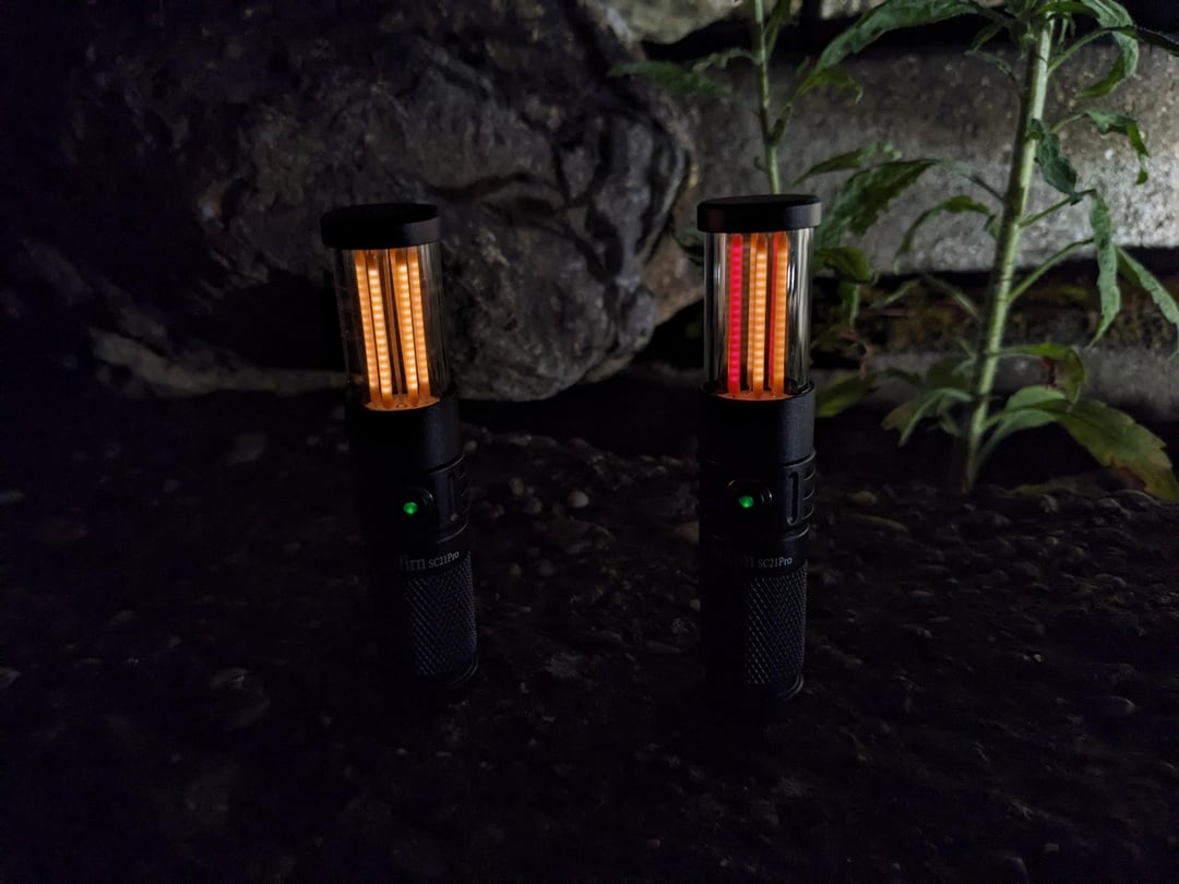
After taking inspiration from u/LuzJoao and u/lumenheir, I guess you could call this version 3 of the Sofirn SC21 LED filament mod.
I tried doing some things different however. I wanted the build to look cleaner with less visible solder points. Also, I did not want to mechanically modify the flashlight itself. All modifications here are fully reversible.
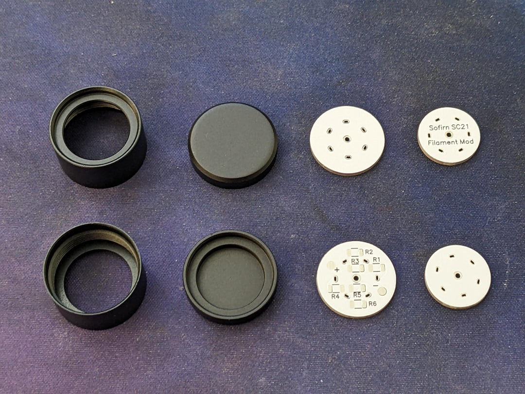
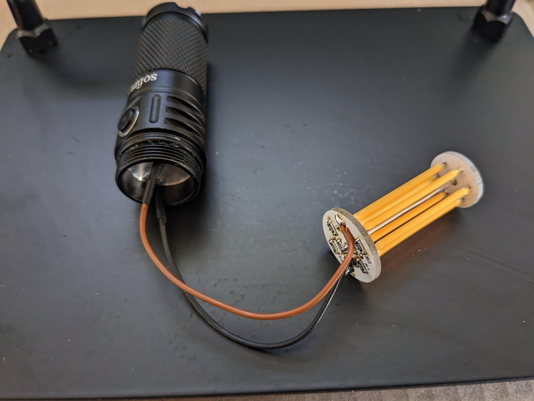
This led to designing two custom PCBs, as well as two mechanical parts which were machined from aluminum and anodized black. All these parts were manufactured by JLCPCB.
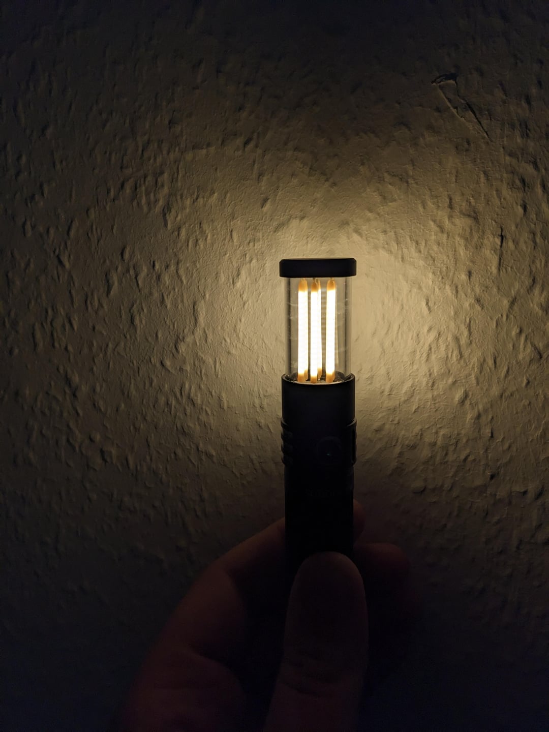
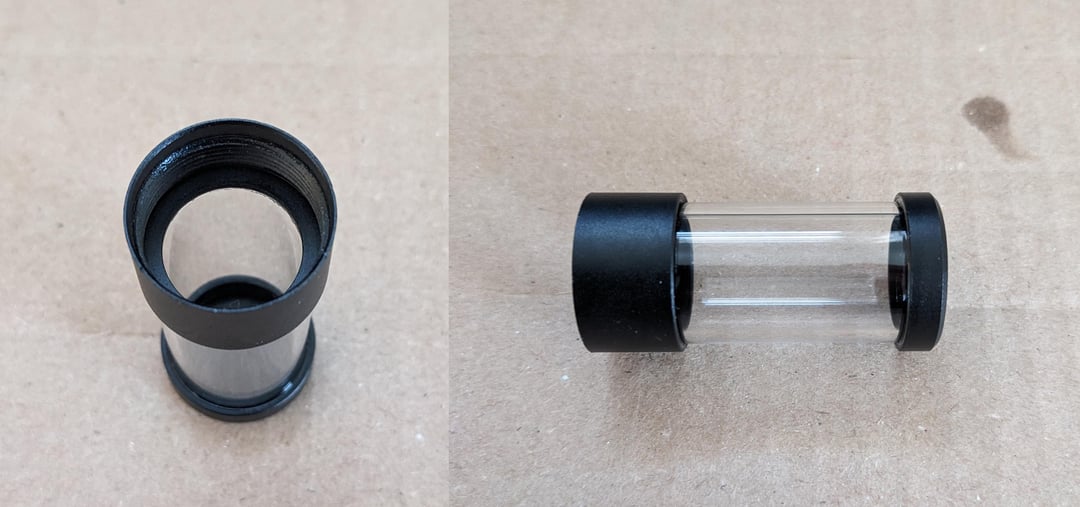
The custom housing is made by cutting a tube of 20 mm borosilicate glass to length and gluing it to the aluminum parts using low viscosity UV glue.
The filaments are soldered between the two PCBs. All the filaments are wired in parallel. The lower PCB allows adding a series resistor to each filament, which can be used to match the brightness of different CCT filaments. For now I only used 0 Ohm resistors.
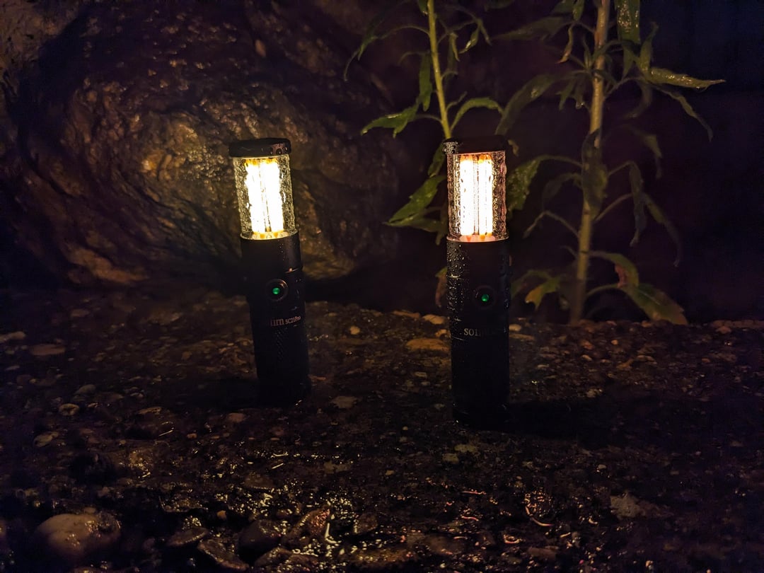
This modification was really expensive (especially the aluminum parts), but I am quite happy with the results. I also ordered some filaments in different CCTs and different lengths and want to test them. In total, I ordered enough parts to make at least 10 of these. I also plan to create detailed instructions, including the gerber and step files in the next weeks if you’re interested.


")
2 Comments
After taking inspiration from u/LuzJoao and u/lumenheir, I guess you could call this version 3 of the Sofirn SC21 LED filament mod.
I tried doing some things different however. I wanted the build to look cleaner with less visible solder points. Also, I did not want to mechanically modify the flashlight itself. All modifications here are fully reversible.
This led to designing two custom PCBs, as well as two mechanical parts which were machined from aluminum and anodized black. All these parts were manufactured by JLCPCB.
The custom housing is made by cutting a tube of 20 mm borosilicate glass to length and gluing it to the aluminum parts using low viscosity UV glue.
The filaments are soldered between the two PCBs. All the filaments are wired in parallel. The lower PCB allows adding a series resistor to each filament, which can be used to match the brightness of different CCT filaments. For now I only used 0 Ohm resistors.
This modification was really expensive (especially the aluminum parts), but I am quite happy with the results. I also ordered some filaments in different CCTs and different lengths and want to test them. In total, I ordered enough parts to make at least 10 of these. I also plan to create detailed instructions, including the gerber and step files in the next weeks if you’re interested.
These look really clean. Very nice work!